TM-9-2350-311-34-2 - Page 275 of 552
TM 9-2350-311-34-2
8
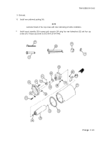
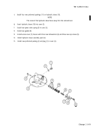
Secure power pack assembly (7) to hose clamp (9) by installing new self-locking nut (8).
9
Insert 0.002 feeler gage between power pack assembly (7) and hose clamp (9) in vicinity of T-bolt (49).
Tighten hose clamp by adjusting self-locking nut (8) until feeler gage cannot be pulled loose. Back off self-
locking nut slightly to remove feeler gage then tighten self-locking nut 1-1/4 to 1-1/2 turns.
10
Remove machine bolt (5) and lockwasher (6) at top of power pack assembly (7). Install sight gage (4) and
secure at top of power pack assembly (7) with lockwasher (6) and machine bolt (5).
11
Secure pressure gage (3) and lower end of sight gage (4) to power pack support (2) with two cap screws
(1).
Change 2
6-13
Back to Top


