TM-9-2350-311-34-2 - Page 274 of 552
TM 9-2350-311-34-2
6-1
POWER PACK ASSEMBLY-CONTINUED
e. Installation
1
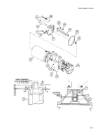
If removed, install hose clamp (9), two headless pins (15.4) and four new cotter pins (15.3).
2
Install ring spacer (15.2) power pack support (2), four new lockwashers (15.1) and four cap screws (15).
3
Position lifting sling assembly (12) over power pack assembly (7) and secure with two lockwashers (11) and
two cap screws (10).
4
Attach hoist (13) to lifting sling assembly (12). Take up slack in cable.
Be careful not to strike or damage the solenoid or valve.
5
Lower power pack assembly (7) through access hole into cab.
6
Make sure weight of power pack assembly (7) is supported by hoist (13). Secure power pack assembly to
power pack support (2) with two cap screws (14).
7
Remove hoist (13). Remove two cap screws (10) to remove lifting sling assembly (12) from power pack
assembly (7). Replace cap screws and two new lockwashers (11). Torque cap screws to 20-25 lb-ft (27-34
N•m).
6-12 Change 2
Back to Top

