TM-9-2520-215-34 - Page 232 of 508
TM 9--2520--215--34
0045 00--4
OUTPUT REDUCTION GEAR OUTPUT SHAFT HOUSING AND RING GEAR
ASSEMBLIES REPLACEMENT – CONTINUED
0045 00
INSTALLATION
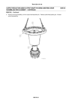
1. Smooth sealing surface (7) prior to installation.
2. Position output shaft assembly (5) on studs (8). Install new preformed packing (6). Coat bearing (9) with white
lead. Install housing assembly (2).
3. Install eight drilled head bolts (4) by rotating housing assembly (2) on output shaft assembly (5) and installing
successively through cut--out (10). Tighten eight drilled head bolts (4) to 67 to 80 lb--ft (90.9 to 108.5 N
S
m).
Install new locking wire (3) through head of eight drilled head bolts (4). Paint splines (11) with white lead.
Back to Top

