TM-9-2520-270-34 - Page 441 of 933
TM 9-2520-270-34
35.
36.
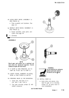
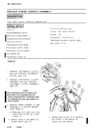
CLEAN INPUT BEVEL ASSEMBLY (1)
AND PINION (2).
a. Clean assembly and hardware. See
page 2-2.
INSPECT INPUT BEVEL ASSEMBLY (1)
AND PINION (2).
a. Inspect assembly, piece parts, and
inserts. See page 2-5.
b. (Deleted)
NOTE
Bevel gear and pinion are a matched set
and must be replaced together. Serial
numbers of gear set must match.
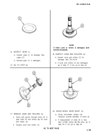
37. IF GEAR (3) WAS REMOVED, GO TO
STEP 38. IF NOT, GO TO STEP 41.
38. VERIFY SERIAL NUMBERS ON BEVEL
GEAR (4) AND PINION (2) MATCH.
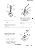
39. PREPARE GEAR (3) FOR MOUNTING.
a.
b.
Using oven, heat gear (3) to
270° -300° F (132° -149° C).
Coat gear mounting surface (5) with
sealant compound.
WARNING
Do not handle hot or cold parts
without protective gloves.
Personnel can be iniured.
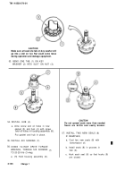
40. INSTALL GEAR (3).
a. Using pliers and gloves, fully
seat hot gear (3) on mounting
surface (5). Let parts return to
room temperature.
GO TO NEXT PAGE
Change
2
4-133
ASSEMBLE
Back to Top

