TM-9-2520-270-34 - Page 798 of 933
:,,: ci,*
2 . . L
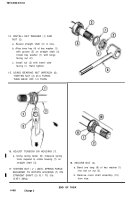
21. REMOVE LJNK (l).,
.;
a. Using
3/8+qh drive, ratchet handle
and 3/8-inch sock&remove and
discard self-locking n&‘.(2). c,
b. Remove bolt (3), sleeve bushjng,(4),, ~
and link (1). Discard bolt.
23. INSTALL CROSS SHAFT
ASSEMBLY (5).
-.
,~
:
Change 3
22. INSPECT LINK ( 1 ), AND SLEEVE
,BUSHINC(4).
.:;
‘,
1
a. Inspect link ( 1 ), and sleeve bushing ( 4 )
for-damage. See page 2:5.
CAUTION
CAUTION
Slot l,n crosg- .shaft must face contrqller
Slot l,n crosg- .shaft must face contrqller
opening. If not, damage to equipment can
opening. If not, damage to equipment can
;&&&;
;&&&;
,I
*-*-.,;
,.
,
,I
*-*-.,;
,.
,
1
-
1
-
24.
CCNNECT LINKS (1) AND (6)+~
24.
CCNNECT LINKS (1) AND (6),+~
a. Positron slot (7) to face controller
a. Positron slot (7) to face controller
opening (8).
opening (8).
b: Position,link’.(i) ir&de~of~link:@).
b: Position,link’.(i) ir&de~of~link:@).
>*
>d
Aline holesand-
instdl new bolt. (9)
Aline holesand-
instdl new bolt. (9)
and.sleeve bushing (10).
and.sleeve bushing (10).
c. Install new self-locking nut (11).
c. Install new self-locking nut (11).
>’
.“:
Back to Top


