TM-9-2520-272-40 - Page 165 of 620
TM 9-2520-272-40
0022
SUSTAINMENT MAINTENANCE
REPAIR LEFT BRAKE APPLY SHAFT ASSEMBLY
INITIAL SETUP:
Tools and Special Tools
Gage, Vernier Caliper, 0-6” (WP 0079, Item 18)
Tool Kit, General Mechanic’s (GMTK) (WP 0079,
Item 45)
Materials/Parts
Pin, Spring (WP 0080, Item 23)
Personnel Required
Track Vehicle Repairer, 91H10
Equipment Condition
Transmission removed from vehicle or container (TM
9-2350-277-13&P)
Oil f ll tube assembly removed (WP 0006)
Left brake apply shaft assembly removed (WP 0021)
REPAIR LEFT BRAKE APPLY SHAFT ASSEMBLY
Remove Pin
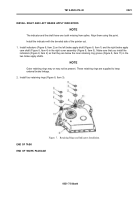
1. Remove spring pin (Figure 1, Item 1) from left brake apply shaft (Figure 1, Item 2). Discard pin (Figure 1, Item 1).
Install Pin
1. Install new spring pin (Figure 1, Item 1) in left brake apply shaft (Figure 1, Item 2) to a depth of 0.027 to 0.047
in. (0.68 to 1.19 mm) below external surface of left brake apply shaft (Figure 1, Item 2).
Back to Top


