TM-9-2520-272-40 - Page 247 of 620
TM 9-2520-272-40
0030
NOTE
The retaining rings on the two ends of the steer shaft are stops. Do not replace retaining rings
that are in good condition.
If necessary, remove retaining rings with f at-tip screwdriver.
Install one of the two ends of the inner (left) steer shaft. Steer shaft is interchangeable.
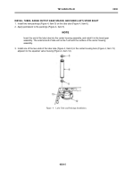
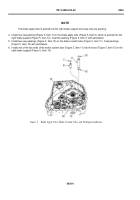
7. Install the inner (left) steer shaft (Figure 6, Item 1) in the bore (Figure 6, Item 17) in the right brake support
(Figure 6, Item 14).
NOTE
Do Step 8 only if sleeve (range output gear spacer) was removed. Early models of the
X200-4A Transmission had a sleeve installed. This sleeve was used when older carrier and
shouldered shaft parts were installed. This sleeve is not installed in later models of the X200-4A
Transmission. Refer to TM 9-2520-272-40P for the current conf guration.
8. Install sleeve (Figure 6, Item 4) on shaft and bushing assembly (Figure 6, Item 3).
Back to Top

