TM-9-2520-272-40 - Page 245 of 620
TM 9-2520-272-40
0030
INSTALL TUBES, RANGE OUTPUT GEAR SPACER, AND INNER (LEFT) STEER SHAFT
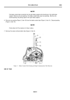
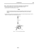
1. Install two new packings (Figure 4, Item 5) on the lube tube (Figure 4, Item 6).
2. Apply petrolatum to the packings (Figure 4, Item 5).
NOTE
Insert the end of the lube tube into the center housing assembly, and install it in the bevel gear
assembly. The external end of tube will not be f ush with the surface of the center housing
assembly.
3. Install one of the two ends of the lube tube (Figure 4, Item 6) in the center housing bore (Figure 4, Item 13)
adjacent to the equalizer valve housing (Figure 4, Item 12).
Back to Top


