TM-9-2815-200-35
ENGINE, WITH CONTAINER:TURBOSUPERCHARGED, DIESEL ,FUEL INJECTION ,90-DEGREE “V” TYPE, AIR - COOLED ,12 - CYLINDER , ASSEMBLY ;MODELS AVDS-1790-2M (2815-856-4996), AVDS-1790-2A AND AVDS-1790-2AM (2815-856-9005)
TECHNICAL MANUAL; DIRECT SUPPORT, GENERAL SUPPORT AND DEPOT MAINTENANCE MANUAL INCLUDING REPAIR PARTS AND SPECIAL TOOLS LISTS
TM-9-2815-200-35 - Page 11 of 779
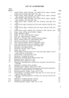
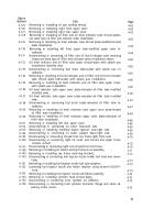
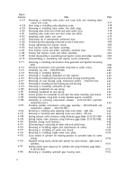
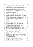
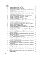
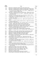
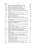
LIST OF ILLUSTRATIONS
Figure
Number
1-1
1-2
1-3
1-4
1-5
1-6
1-7
1-8
1-9
1-10
1-11
1-12
1-13
1-14
1-15
1-16
2-1
2-2
2-3
2-4
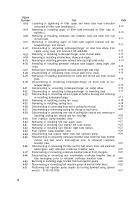
4-1
4-2
4-3
4-4
4-5
4-6
4-7
4-8
4-9
4-10
4-11
4-12
4-13
4-14
4-15
4-16
4-17
Title
AVDS-1790-2M, AVDS-1790-2AM, and AVDS-1790-2A engine assembly
without time totalizing meter-right front view.
AVDS-1790-2M, AVDS-1790-2AM, and AVDS-1790-2A engine assembly
with secondary fuel filter-left front view.
AVDS-1790-2M, AVDS-1790-2AM, and AVDS-1790-2A engine assembly
with secondary fuel filter-front view.
AVDS-1790-2A engine assembly with time totalizing meter-right front
view.
AVDS-1790-2A engine assembly with fuel/ water separator filter-left front
view.
AVDS-1790-2A engine assembly with fuel/ water separator filter-front
view.
AVDS-1790-2A engine assembly with relocated oil filler tube-rear view.
Engine major working parts-schematic diagram.
Engine lubrication system.
Engine oil flow control-schematic diagram.
Main fuel system-schematic diagram.
Manifold air induction heater system-schematic diagram.
Piston actuated cooling fan clutch-sectional view.
Mechanical cooling fan clutch-sectional view.
Early crankcase breather and fire extinguisher system.
Late crankcase breather and fire extinguisher system.
Improvised tools-ring compressor, and lifting tool.
Improvised tool-coupling puller.
Improvised tool-valve sleeve remover.
Typical shop layout.
Disconnecting or connecting fuel hose at fuel pump outlet adapter and fuel
pump inlet tube at fuel pump.
Disconnecting or connecting fuel pump.
Removing or installing fuel pump.
Removing or installing starter solenoid jumper lead.
Removing starter retaining “U” bolt.
Removing starter support and cradle.
Removing or installing starter mounting nuts using open end wrench-5120-
678-5288.
Removing or installing starter assembly.
Installing starter support, cradle, and “U” bolt,
Disconnecting or connecting time totalizing meter electrical lead at generator.
Removing or installing generator air intake tube.
Removing generator support, cradle, and “U” bolt.
Disconnecting or connecting cylinder head right rear oil drain tube and
generator boot hose clamps.
Loosening or tightening generator mounting nuts using box wrench-5120-
789-4881.
Removing or installing generator and boot.
Removing or installing generator gasket.
Installing generator support, cradle, and “U” bolt.
Page
. . .
xxviii
xxix
xxx
xxxi
xxxii
. . .
xxxiii
xxxiv
1-5
1-9
1-11
1-13
1-15
1-17
1-18
1-19
1-20
2-2
2-3
2-4
2-7
4-2
4-3
4-3
4-3
4-4
4-4
4-4
4-5
4-5
4-6
4-6
4-7
4-7
4-8
4-8
4-9
4-9
v
Back to Top

