TM-9-2815-200-35
ENGINE, WITH CONTAINER:TURBOSUPERCHARGED, DIESEL ,FUEL INJECTION ,90-DEGREE “V” TYPE, AIR - COOLED ,12 - CYLINDER , ASSEMBLY ;MODELS AVDS-1790-2M (2815-856-4996), AVDS-1790-2A AND AVDS-1790-2AM (2815-856-9005)
TECHNICAL MANUAL; DIRECT SUPPORT, GENERAL SUPPORT AND DEPOT MAINTENANCE MANUAL INCLUDING REPAIR PARTS AND SPECIAL TOOLS LISTS
TM-9-2815-200-35 - Page 14 of 779
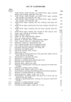
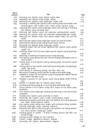
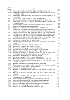
Figure
Number
4-87
4-88
4-89
4-90
4-91
4-92
4-93
4-94
4-95
4-96
4-97
4-98
4-99
4-100
4-101
4-102
4-103
4-104
4-105
4-106
4-107
4-108
4-109
4-110
4-111
4-112
4-113
4-114
4-115
4-116
4-117
4-118
4-119
4-120
4-121
4-122
4-123
4-124
. . .
viii
Title
Front fan drive housing fan rotor hub sleeve spacer-4910-795-7952 in-
stalled for leakage test.
Checking cooling fan blade clearance.
Removing or installing main oil filter bypass valve plug, gasket and spring.
Removing or installing main oil filter bypass valve.
Removing or installing auxiliary oil filter bypass valve plug, gasket, and
spring.
Removing or installing auxiliary oil filter bypass valve.
Removing or installing engine oil pressure regulating valve.
Disconnecting or connecting fuel/ water separator filter inlet hose at fuel
pump.
Disconnecting or connecting fuel hoses and drain line at fuel/ water
separator filter.
Removing or installing fuel/ water separator filter assembly.
Removing or installing fuel/ water separator filter cover bolts.
Removing or installing fuel/ water separator filter cover.
Removing or installing rear fan drive housing cover attaching parts.
Removing or installing rear fan drive housing cover and clutch assembly.
Removing or installing fan drive housing cover preformed packing.
Comparison between piston actuated and mechanical fan drive housing and
cover assemblies.
Removing housing cover and bearing from vertical drive shaft.
Removing fan drive clutch upper ball bearing from housing cover.
Pressing fan drive clutch upper ball bearing into housing cover.
Disconnecting or connecting cylinder head oil drain tube hoses-cylinders 1 L
and 2L.
Disconnecting or connecting intermediate cylinder head oil drain tubes-
cylinder 2L.
Rem oving or installing intermediate cylinder head oil drain tube-cylinder
2L.
Disconnecting or connecting intake manifold tube from intake manifold and
cylinder 2L.
Removing or installing intake manifold tube-cylinder
2L.
Left intake manifold-installed view.
Disconnecting or connecting manifold heater fuel inlet tube.
Disconnecting or connecting cylinder head oil drain tube-left front.
Disconnecting or connecting cylinder head oil drain tube-left rear.
Disconnecting or connecting heater fuel inlet and outlet tubes from intake
manifold heater
Disconnecting or connecting turbosupercharger air outlet elbow and heater
tube.
Removing or installing intake manifold assembly-left side.
Disassembling or assembling intake manifold assembly.
Disconnecting or connecting right front cylinder head oil drain tube.
Disconnecting or connecting left rear cylinder head oil drain tube.
Disconnecting or connecting right rear cylinder head oil drain tube.
Disconnecting or connecting oil filler and oil level indicator tubes from oil
pan.
Removing or installing
Removing or installing
oil pan rear bolts,
engine oil pan.
Page
4-44
4-44
4-45
4-45
4-46
4-46
4-47
4-48
4-48
4-49
4-49
4-49
4-50
4-50
4-51
4-51
4-52
4-52
4-52
4-53
4-53
4-53
4-54
4-54
4-55
4-55
4-56
4-56
4-56
4-57
4-57
4-58
4-59
4-59
4-60
4-60
4-61
4-61
Back to Top


