TM-9-2815-200-35
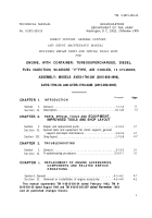
ENGINE, WITH CONTAINER:TURBOSUPERCHARGED, DIESEL ,FUEL INJECTION ,90-DEGREE “V” TYPE, AIR - COOLED ,12 - CYLINDER , ASSEMBLY ;MODELS AVDS-1790-2M (2815-856-4996), AVDS-1790-2A AND AVDS-1790-2AM (2815-856-9005)
TECHNICAL MANUAL; DIRECT SUPPORT, GENERAL SUPPORT AND DEPOT MAINTENANCE MANUAL INCLUDING REPAIR PARTS AND SPECIAL TOOLS LISTS
TM-9-2815-200-35 - Page 17 of 779
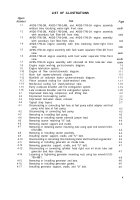
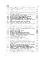
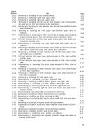
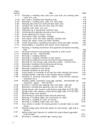
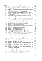
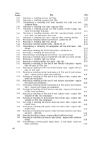
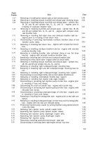
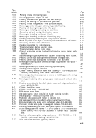
Figure
Number
4-199
4-200
4-201
5-1
5-2
5-3
5-4
5-5
5-6
5-7
5-8
5-9
5-10
5-11
5-12
5-13
5-14
5-15
5-16
5-17
5-18
5-19
5-20
5-21
5-22
5-23
5-24
5-25
5-26
5-27
5-28
5-29
5-30
5-31
5-32
5-33
5-34
Title
Removing or installing camshaft drive gearshaft plug retaining ring.
Removing or installing camshaft drive gearshaft plug using mechanical puller
Removing or installing camshaft drive shaft using mechanical puller -5120-
678-5282.
Lifting engine using multiple leg sling - 4910-919-2884.
Removing or installing oil pan drain plugs (Model AVDS-1790-2-M ).
Removing or installing oil pan drain plugs (Models AVDS-1790-2AM and
AVDS-1790-2A).
Disconnecting or connecting time totalizing meter electrical lead clamps.
Removing or installing time totaliz.ing meter.
Engine on maintenance and overhaul stand - 4910-856-4137.
Removing or installing oil filler and oil level indicator tube shroud plate oil
drain hose - engines with oil filler and indicator with splash pan drain,
Removing or installing oil filler and oil level indicator tube shroud plate and
oil drain hose - engines with oil filler and indicator with splash pan drain
Oil filler and oil level indicator tube shroud plate oil drain hose grommet -
installed view - engines with oil filler and indicator with splash pan drain.
Removing or installing manifold heater ignition unit - right side.
Removing or installing right oil cooler screens.
Disconnecting or connecting right oil cooler hose and primary fuel filter drain
tubes.
Removing or installing oil cooler to support bolts.
Removing or installing right engine oil cooler.
Removing or installing right transmission oil cooler.
Disconnecting or connecting upper cover frame - right front view.
Disconnecting or connecting upper cover frame - right rear view.
Removing or installing oil indicator and oil filler tube to upper frame
retaining strap - left side engines without relocated oil filler tube.
Removing or installing right oil cooler end shroud.
Rem oving or installing right oil cooler support beam.
Removing or installing upper cover frame support brackets - right side.
Rem oving or installing right turbosupercharger oil inlet hose and trans-
mission shroud.
Removing or installing right manifold heater fuel return tube.
Disconnecting or connecting manifold heater fuel inlet tube at manifold
heater and cylinder head oil drain manifolds.
Removing or installing fuel check valve.
Removing or installing manifold heater fuel inlet solenoid valve and fuel
filter.
Removing or installing manifold heater fuel return solenoid valve and
bracket.
Removing or installing right rear cylinder head oil drain tube and tur-
bosupercharger oil drain tube.
Disconnecting or connecting right front cylinder head oil drain tube.
Disconnecting or connecting left front cylinder head oil drain tube.
Disconnecting or connecting left rear cylinder head oil drain tube.
Removing or installing right cylinder head oil drain manifold tubes.
Removing or installing right intake manifold.
Removing or installing primary fuel filter drain tube.
Page
4-102
4-102
4-102
5-1
5-2
5-2
5-3
5-3
5-4
5-5
5-5
5-6
5-6
5-7
5-8
5-8
5-9
5-9
5-9
5-10
5-10
5-11
5-11
5-12
5-13
5-13
5-14
5-14
5-15
5-15
5-16
5-16
5-16
5-17
5-17
5-1’8
5-19
x i
Back to Top

