TM-9-2815-200-35
ENGINE, WITH CONTAINER:TURBOSUPERCHARGED, DIESEL ,FUEL INJECTION ,90-DEGREE “V” TYPE, AIR - COOLED ,12 - CYLINDER , ASSEMBLY ;MODELS AVDS-1790-2M (2815-856-4996), AVDS-1790-2A AND AVDS-1790-2AM (2815-856-9005)
TECHNICAL MANUAL; DIRECT SUPPORT, GENERAL SUPPORT AND DEPOT MAINTENANCE MANUAL INCLUDING REPAIR PARTS AND SPECIAL TOOLS LISTS
TM-9-2815-200-35 - Page 131 of 779
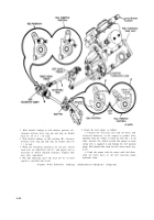
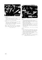
Remove
1. Remove lower two cap screws (A), lock washers, and
plain washers.
2. Remove upper two cap screws (B) and lock washers
and remove filter assembly from bracket.
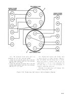
Remove
1. Remove cover (A).
2. Remove and discard preformed packing (B).
Install
Note.
Replacement coalescer elements an d
preformed packing are available in parts kit -
2910-801-1152. Purge fuel system, refer t o
pertinent operator’s manual .
1. Install new preformed packing (B).
2. Install cover (A).
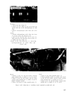
Figure 4-98 Removing or installin g
Note.
Fuel inlet, outlet, and drain elbows are
fuel / water separator filter cover .
not part of the filter assembly and must be in -
stalled in the replacement filter .
Install
1. Position filter assembly on bracket and install upper
two cap screws (B) and lock washers.
2. Install lower two cap screws (A), lock washers, and
plain washers.
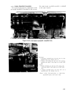
Figure 4-96. Removing or installin g
fuel / water separator filter assembly .
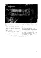
Note.
Entire area around the fuel / wate r
separator filter should be thoroughly cleaned to
prevent the entry of dirt or other foreign objects
before removing the cover .
Figure 4-97. Removing or installin g
fuel / water separator filter cover bolts .
4-49
Back to Top


