TM-9-2815-200-35
ENGINE, WITH CONTAINER:TURBOSUPERCHARGED, DIESEL ,FUEL INJECTION ,90-DEGREE “V” TYPE, AIR - COOLED ,12 - CYLINDER , ASSEMBLY ;MODELS AVDS-1790-2M (2815-856-4996), AVDS-1790-2A AND AVDS-1790-2AM (2815-856-9005)
TECHNICAL MANUAL; DIRECT SUPPORT, GENERAL SUPPORT AND DEPOT MAINTENANCE MANUAL INCLUDING REPAIR PARTS AND SPECIAL TOOLS LISTS
TM-9-2815-200-35 - Page 140 of 779
Disassemble
Assemble
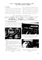
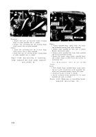
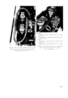
1. Remove six nuts (A) and flat washers attaching intake
1. Install intake manifold tubes for cylinders 1L, 2L, 5L,
manifold elbow to intake manifold. Remove elbow and
and 6L following instructions accompanying figure 4-
heater tube as a unit. Remove and discard gasket.
110.
2. Remove four nuts (B) attaching intake manifold tubes
2. Install new gaskets on studs on intake manifold for
3L and 4L to intake manifold and remove tubes,
cylinders 3L and 4L intake manifold tubes. Position
Remove and discard gaskets.
tubes on manifold and install four nuts (B) securing
3. Remove intake manifold tubes for cylinders 1L, 2L,
each tube to manifold.
5L, and 6L following instructions accompanying figure
3. Install new intake manifold elbow gasket on manifold
4-110.
studs. Position intake manifold elbow and heater tube
as a unit on manifold. Install six nuts (A) and flat
washers securing elbow to manifold.
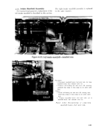
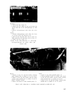
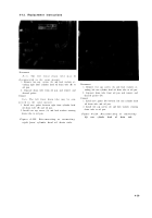
Figure 4-118. Disassembling or assembling intake manifold assembly .
Section
VI.
REPLACEMENT
OF
ENGINE
OIL
PAN
4-12. General
This section covers the replacement of th e
removal and installation of the oil pan. Figur e
engin e
oil pan .
Refer
to
Table
4-5
for
references are listed under appropriate heading s
illustration s
an d
instruction s
coverin g
th e
in the table .
Table 4-5. Engine Oil Pan
4-58
Back to Top

