TM-9-2815-200-35
ENGINE, WITH CONTAINER:TURBOSUPERCHARGED, DIESEL ,FUEL INJECTION ,90-DEGREE “V” TYPE, AIR - COOLED ,12 - CYLINDER , ASSEMBLY ;MODELS AVDS-1790-2M (2815-856-4996), AVDS-1790-2A AND AVDS-1790-2AM (2815-856-9005)
TECHNICAL MANUAL; DIRECT SUPPORT, GENERAL SUPPORT AND DEPOT MAINTENANCE MANUAL INCLUDING REPAIR PARTS AND SPECIAL TOOLS LISTS
TM-9-2815-200-35 - Page 135 of 779
Section V. REPLACEMENT OF INTAKE MANIFOLD TUBES
AND INTAKE MANIFOLD ASSEMBLY
4-9. General
This section covers the replacement of intake
manifold tubes an d
the intak e
manifol d
assembly. Intake manifold tubes for cylinder 1 ,
2, 5, and 6, on each side of the engine can b e
replaced without removing the complete intak e
manifold. Intake manifold tubes for cylinder 3
and 4 on each side of engine cannot be replaced
unless the complete intake manifold system i s
removed from the engine. In order to remove any
cylinder intake manifold tube, it is necessary to
remove the oil drain tube on that cylinder. Refer
to Table 4-4 for illustrations and instructions on
removal and installation of the manifold tubes or
manifold assemblies. Figure references are listed
under appropriate headings in the table .
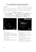
Table 4-4. Intake Manifold Tubes and Intake Manifold Assembly
4-10. Intake Manifold Tubes
For instructional purposes replacement o f
intake manifold tube for cylinder 2L is described
in this section. Tubes for cylinders lL, 5L, 6L ,
lR, 2R, 5R, and 6R are replaced in the sam e
manner .
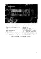
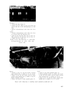
Figure 4-107. Disconnecting or connectin g
intermediate cylinder head oil drai n
tubes - cylinder 2L .
Disconnect
1. Loosen four hose clamps (A) and side hoses from
intermediate cylinder head oil drain tube.
2. Remove screw and nut attaching flame heater fuel
inlet line cushioned clamp (B) to loop clamp on cylinder
head oil drain tube, if necessary.
Connect
1. Install screw and nut securing flame heater fuel inlet
line cushioned clamp (B) to loop clamp on cylinder
head oil drain tube.
2. Slide hoses on intermediate cylinder head OR drain
tube and tighten four hose clamps (A).
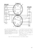
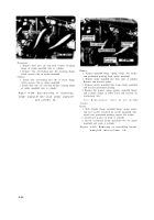
Figure 4-106. Disconnecting or connectin g
cylinder head oil drain tube hoses-cylinder s
IL and 2L .
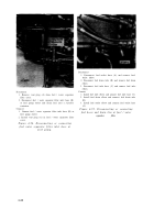
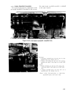
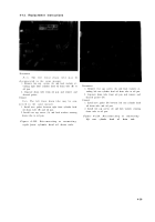
Figure 4-108. Removing or installing inter -
mediate cylinder head oil drain tube -
cylinder 2L .
4-5 3
Back to Top

