TM-9-2815-200-35
ENGINE, WITH CONTAINER:TURBOSUPERCHARGED, DIESEL ,FUEL INJECTION ,90-DEGREE “V” TYPE, AIR - COOLED ,12 - CYLINDER , ASSEMBLY ;MODELS AVDS-1790-2M (2815-856-4996), AVDS-1790-2A AND AVDS-1790-2AM (2815-856-9005)
TECHNICAL MANUAL; DIRECT SUPPORT, GENERAL SUPPORT AND DEPOT MAINTENANCE MANUAL INCLUDING REPAIR PARTS AND SPECIAL TOOLS LISTS
TM-9-2815-200-35 - Page 126 of 779
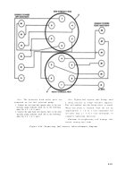
Figure 4-88.
Note.
The fuel injection pump, fuel tubes, and
fuel tube connections must be checked for fue l
leaks with the engine running before the cooling
fans are installed .
Caution:
Do not run engine above idle an d
not longer than ten minutes without cooling fans.
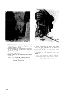
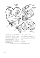
1. Install a fan rotor hub sleeve spacer -4910-795-7952
(A) on each fan drive vertical drive shaft to prevent oil
seepage at fan drive oil seals while operating engine.
2. Secure the sleeve spacer (A) to each drive shaft with
the same nut (B) used to secure the cooling fan. Start
engine and check for fuel leaks. If leaks are evident
loosen the tube fittings and retighten. Replace fuel
injection tubes if leak persists.
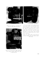
3. Slide the 12 fuel injector tube dust caps (C) over tube
fittings at fuel injection pump hydraulic head.
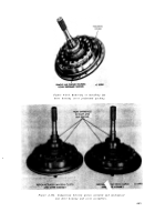
Figure 4-87. Front fan drive housing fa n
rotor hub sleeve spacer-4910-795-795 2
installed for leakage test .
Section
Ill.
REPLACEMENT
OF
MAIN
AND
AUXILIARY
OIL
VALVE, OIL PRESSURE REGULATOR VALVE
FUEL
/
WATER
SEPARATOR
FILTER
FILTER BYPAS S
AN D
4-5. General
This section covers the replacement of th e
The two outer elements in the fuel / wate r
main and auxiliary oil filter bypass valves, the oil
separator filter are periodic maintenance item s
pressure regulating valve, and the fuel / wate r
and are allocated to the organizational main -
separator filter. The valves are not periodi c
tenance personnel. These are coalescer element s
maintenance items, and should only be removed
designate d
to separate water fro m
the fue l
for inspection or replaced in case of malfunction.
system. The center element is a final fuel filte r
4-44
Back to Top

