TM-9-2815-200-35
ENGINE, WITH CONTAINER:TURBOSUPERCHARGED, DIESEL ,FUEL INJECTION ,90-DEGREE “V” TYPE, AIR - COOLED ,12 - CYLINDER , ASSEMBLY ;MODELS AVDS-1790-2M (2815-856-4996), AVDS-1790-2A AND AVDS-1790-2AM (2815-856-9005)
TECHNICAL MANUAL; DIRECT SUPPORT, GENERAL SUPPORT AND DEPOT MAINTENANCE MANUAL INCLUDING REPAIR PARTS AND SPECIAL TOOLS LISTS
TM-9-2815-200-35 - Page 123 of 779
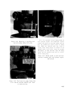
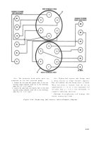
Figure 4-83.
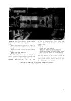
Figure 4-84.
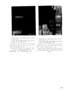
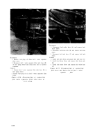
figure 4-85
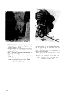
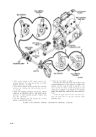
1. Using two 5 / 16-in. steel rods (A) hold fuel injection
pump drive coupling flange (nearest the pump)
stationary and rotate the other coupling half coun-
terclockwise to remove backlash from the pump drive
shaft.
2. Making certain timing marks (B) are a lined and
backlash is removed, position pilot ring (C) on coupler
half and install four lock washers and bolts.
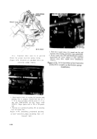
Figure 4-82. Removing fuel injection pum p
drive gear train backlash and setting advance
unit retard position-diaphragm coupler .
4-41
Back to Top


