TM-9-2815-200-35
ENGINE, WITH CONTAINER:TURBOSUPERCHARGED, DIESEL ,FUEL INJECTION ,90-DEGREE “V” TYPE, AIR - COOLED ,12 - CYLINDER , ASSEMBLY ;MODELS AVDS-1790-2M (2815-856-4996), AVDS-1790-2A AND AVDS-1790-2AM (2815-856-9005)
TECHNICAL MANUAL; DIRECT SUPPORT, GENERAL SUPPORT AND DEPOT MAINTENANCE MANUAL INCLUDING REPAIR PARTS AND SPECIAL TOOLS LISTS
TM-9-2815-200-35 - Page 122 of 779
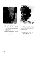
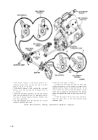
Figure 4-80
1. Using two 5 / 16-in. steel rods (A), hold fuel injection
pump
drive
coupler
sleeve
(nearest
the
pump)
stationary and rotate the other drive coupler sleeve
counterclockwise to remove backlash from the pump
drive shaft.
2. When backlash is removed and flat sides of drive
coupler mate, tighten four drive coupler bolts (B)
securely.
3. When flat sides of drive coupler sleeves (C) do not
mate when backlash is removed, the coupler sleeves
must be separated and reset. Separate coupler and push
sleeve of drive coupler on rear fan and accessory drive
housing (fig. 4-75) shaft toward drive shaft and from
hub splines. Adjust sleeve on splines so flat sides of
coupler half are alined. Torque tighten coupler bolts.
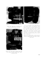
Lubricate drive coupler (fig. 4-80).
Figure 4-79. Removing fuel injection pum p
drive gear train backlash and setting
advanced unit retard position-spline d
coupler .
4-40
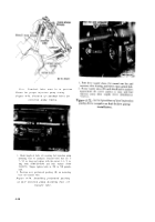
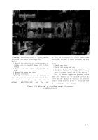
Note.
For proper assembly of coupler half to
diaphragm pack, place a pry bar between rea r
fan and accessory drive housing and coupler half
and apply pressure to take up the end thrust o f
drive gear. Measure clearance between couple r
half and diaphragm pack. This clearance canno t
exceed 0.050-inch or it will put undue stress on
the diaphragm pack causing early failure. If the
0.050-inch dimension cannot be achieved, it wil l
be necessary to remove fuel injection pump and
replac e
coupler hall or complete couplin g
assembly. Torque coupler half retaining nut t o
900 inch-pounds whe n
installing new couple r
half .
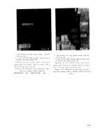
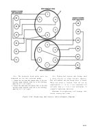
Figure 4-81. Checking diaphragm couple r
assembly clearance .
Back to Top


