TM-9-2815-200-35
ENGINE, WITH CONTAINER:TURBOSUPERCHARGED, DIESEL ,FUEL INJECTION ,90-DEGREE “V” TYPE, AIR - COOLED ,12 - CYLINDER , ASSEMBLY ;MODELS AVDS-1790-2M (2815-856-4996), AVDS-1790-2A AND AVDS-1790-2AM (2815-856-9005)
TECHNICAL MANUAL; DIRECT SUPPORT, GENERAL SUPPORT AND DEPOT MAINTENANCE MANUAL INCLUDING REPAIR PARTS AND SPECIAL TOOLS LISTS
TM-9-2815-200-35 - Page 118 of 779
Remove
Note.
Before the fuel injection pump is in -
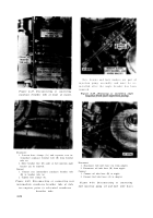
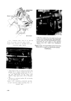
Figure 4-68. Timing marks on fuel injectio n
pump bearing retaining plate and diaphrag m
coupler hub alined .
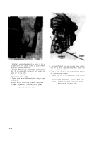
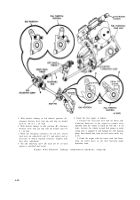
Figure 4-69. Disconnecting or connectin g
primary fuel filter drain line .
stalled on the engine ,
the engine must b e
properly timed with number one right ban k
cylinder in the firing position. In order to se t
engine timing, it is necessary to remove th e
primary fuel filter bracket and throttle linkage to
check position of camshaft. lobes (fig. 4-73) .
1. Remove three screws (A) and lock washers attaching
primary fuel filter bracket and throttle linkage plate to
number 1R cylinder assembly.
2.
Remove
two
bolts
(B)
attaching
throttle
linkage
bracket to crankshaft damper and oil fiber housing.
3. Remove cotter pin, nut (C), flat washer, and bolt and
disconnect rod from lever. Discard cotter pin.
4. Move filter, bracket and plate (D), and throttle
linkage to expose camshaft lobes. Discard gasket.
Install
1. Position filter, bracket and plate (D), and throttle
linkage on engine using new gasket.
2. Install three screws (A) and lock washers securing
primary fuel filter bracket and throttle linkage plate to
number 1R cylinder assembly.
3. Install two bolts (B) securing throttle linkage bracket
to camshaft damper and oil filter housing.
4. Install bolt, flat washer, nut (C), and new cotter pin
connecting rod to lever.
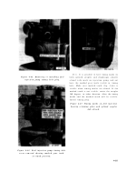
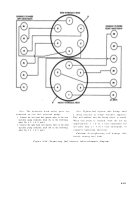
Figure 4-70. Removing or installing primar y
fuel filter bracket and throttle linkage .
4-36
Back to Top

