TM-9-2815-200-35
ENGINE, WITH CONTAINER:TURBOSUPERCHARGED, DIESEL ,FUEL INJECTION ,90-DEGREE “V” TYPE, AIR - COOLED ,12 - CYLINDER , ASSEMBLY ;MODELS AVDS-1790-2M (2815-856-4996), AVDS-1790-2A AND AVDS-1790-2AM (2815-856-9005)
TECHNICAL MANUAL; DIRECT SUPPORT, GENERAL SUPPORT AND DEPOT MAINTENANCE MANUAL INCLUDING REPAIR PARTS AND SPECIAL TOOLS LISTS
TM-9-2815-200-35 - Page 224 of 779
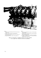
Remove
1. Remove eight self-locking nuts (A) and bolts. Remove
four plates and eight tube clamps from four left tube
clamp supports.
2. Remove four self-locking nuts (B) and bolts. Remove
two plates and four tube clamps from double tube
clamp support.
3. Remove four self-locking nuts (C) and bolts. Remove
four plates and tube clamps.
4. Remove four self-locking nuts (D) and bolts. Remove
four plates and tube clamps.
5. Remove four self-locking nuts (E) and bolts. Remove
two plates and four tube clamps from angle brackets.
6. Remove six self-locking nuts (F) and bolts. Remove
three plates and six tube clamps from three right tube
clamp supports.
Install
1. Position two tube clamps, one under and one over fuel
injector tubes, and plate on top of each clamp at each
right tube clamp support. Install six self-locking nuts
(F) and bolts securing clamps.
2. Position two tube clamps, one under and one over fuel
injector tubes, and plate on top of each clamp at angle
brackets. Install four self-locking nuts (E) and bolts
securing clamps.
3. Position two clamps, one under and one over fuel
injector tubes, and one plate under and one over each
clamp at location shown. Install four self-locking nuts
(D) and bolts securing clamps.
4. Position two clamps, one under and one over outer
two fuel injector tubes at location shown, and one plate
under and one over each clamp. Install four self-locking
nuts (C) and bolts securing clamps.
5. Position two clamps, one under and one over fuel
injector tubes and one plate on top of each clamp at
double tube clamp support. Install four self-locking
nuts (B) and bolts securing clamps.
6. Position two clamps, one under and one over fuel
injector tubes, and plate on top of each clamp at each
left tube clamp support. Install eight self-locking nuts
(A) and bolts securing clamps.
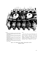
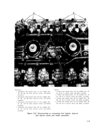
Figure 5-65. Removing or installing fuel injector tube
5-38
clamps-engines with additional clamps.
Back to Top


