TM-9-2815-200-35
ENGINE, WITH CONTAINER:TURBOSUPERCHARGED, DIESEL ,FUEL INJECTION ,90-DEGREE “V” TYPE, AIR - COOLED ,12 - CYLINDER , ASSEMBLY ;MODELS AVDS-1790-2M (2815-856-4996), AVDS-1790-2A AND AVDS-1790-2AM (2815-856-9005)
TECHNICAL MANUAL; DIRECT SUPPORT, GENERAL SUPPORT AND DEPOT MAINTENANCE MANUAL INCLUDING REPAIR PARTS AND SPECIAL TOOLS LISTS
TM-9-2815-200-35 - Page 219 of 779
Fig. 5-61
Fig. 5-64
Fig. 6-58
Fig. 5-71
Fig. 5-79
5-8. Fuel Injector Tubes, Supports, an d
Clamps, Exhaust Pipes and Manifold s
Fuel Inlet and Return Hoses Crankcas e
Breather Tubes, and Turbosupercharge r
Base, Supports and Tie Rod s
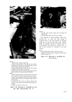
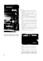
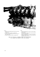
Refer to Table 5-5 for illustrations an d
disassembly instructions. Figure references are
listed in the table.
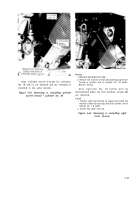
Figure 5-60. Removing or installing oil level
indicator tube cylinder plate-engines
with relocated oil filler tube installation.
Table 5-5. Fuel Injector Tubes, Supports, and Clamps, Exhaust Pipes and
Manifold, Fuel Inlet and Return Hoses, Crankcase Breather Tubes, and
Turbosupercharger Base, Supports and Tie Rods
5-33
Back to Top

