TM-9-2815-200-35
ENGINE, WITH CONTAINER:TURBOSUPERCHARGED, DIESEL ,FUEL INJECTION ,90-DEGREE “V” TYPE, AIR - COOLED ,12 - CYLINDER , ASSEMBLY ;MODELS AVDS-1790-2M (2815-856-4996), AVDS-1790-2A AND AVDS-1790-2AM (2815-856-9005)
TECHNICAL MANUAL; DIRECT SUPPORT, GENERAL SUPPORT AND DEPOT MAINTENANCE MANUAL INCLUDING REPAIR PARTS AND SPECIAL TOOLS LISTS
TM-9-2815-200-35 - Page 217 of 779
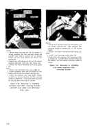
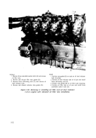
Remove
1. Remove two machine screws (A) and lock washers
and remove cylinder head plate at oil filler tube.
2. Remove two machine screws (B) and lock washer-e
and remove cylinder head plate at oil level indicator
tube.
Install
1. Position cylinder head plate at oil level indicator tube
position. Install two machine screws (B) and lock
washers securing plate.
2. Position cylinder head plate at oil filler tube position.
Install two machine screws (A) and lock washers
securing plate.
Figure 5-57. Removing or installing cylinder
head plates at oil filler and oil level
indicator tubes—engines with
splash pan installation.
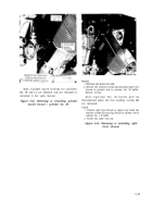
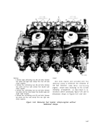
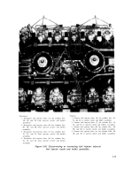
Remove
1. Remove two machine screws (A) and lock washers
and remove oil level indicator tube plate.
2. Remove two machine screws (B) and lock washers
attaching oil level indicator tube cylinder plate.
Install
1. Install two machine screws (B) and lock washers
securing oil level indicator tube cylinder plate.
2. Position oil level indicator tube plate and install two
machine screws (A) and lock washers securing plate.
Figure 5-58. Removing or installing oil level
indicator tube plate-engines with
relocated oil filler tube installation.
5-31
Back to Top


