TM-9-2815-200-35
ENGINE, WITH CONTAINER:TURBOSUPERCHARGED, DIESEL ,FUEL INJECTION ,90-DEGREE “V” TYPE, AIR - COOLED ,12 - CYLINDER , ASSEMBLY ;MODELS AVDS-1790-2M (2815-856-4996), AVDS-1790-2A AND AVDS-1790-2AM (2815-856-9005)
TECHNICAL MANUAL; DIRECT SUPPORT, GENERAL SUPPORT AND DEPOT MAINTENANCE MANUAL INCLUDING REPAIR PARTS AND SPECIAL TOOLS LISTS
TM-9-2815-200-35 - Page 236 of 779
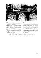
Disconnect
1. Remove cotter pin, slotted nut (A), and bolt attaching
throttle adjustable rod. Remove adjustable rod.
2. Remove cotter pin, slotted nut (B), and bolt attaching
throttle rod to intermediate throttle lever.
3. Remove cotter pin, slotted nut (C), flat washer, and
bolt attaching throttle rod to injection pump lever.
Remove red.
Connect
1. Position throttle rod on injection pump lever. Install
bolt, flat washer, slotted nut (C), and cotter pin
securing rod.
2. Install bolt, slotted nut (B), and cotter pin securing
throttle rod to intermediate throttle lever.
3. Position throttle adjustable rod on intermediate
throttle lever. Install bolt, slotted nut (A), and cotter
pin securing rod.
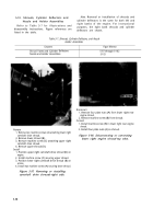
Remove
1. Remove three self-locking nuts (A) attaching in-
termediate throttle lever support to front fan drive
housing.
2. Remove lever support (B), shaft, and throttle lever as
a unit.
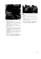
Install
1. Position lever support (B), shaft, and throttle lever as
a unit on front fan drive housing.
2. Install three self-locking nuts (A) securing lever
support to drive housing.
Figure 5-83. Removing or installing
intermediate throttle lever support.
Figure 5-82. Disconnecting or connecting
throttle rods at intermediate throttle lever.
5-50
Back to Top


