TM-9-2815-200-35
ENGINE, WITH CONTAINER:TURBOSUPERCHARGED, DIESEL ,FUEL INJECTION ,90-DEGREE “V” TYPE, AIR - COOLED ,12 - CYLINDER , ASSEMBLY ;MODELS AVDS-1790-2M (2815-856-4996), AVDS-1790-2A AND AVDS-1790-2AM (2815-856-9005)
TECHNICAL MANUAL; DIRECT SUPPORT, GENERAL SUPPORT AND DEPOT MAINTENANCE MANUAL INCLUDING REPAIR PARTS AND SPECIAL TOOLS LISTS
TM-9-2815-200-35 - Page 242 of 779
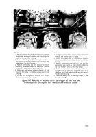
Figure 5-91. Positioning injection pump
coupler by turning flywheel using splined
wrench-5120-793-7895.
Note. The fuel injection pump splined coupler
sleeves
and hubs must be identified with
identical marks to prevent mismating of parts.
The sleeves and hubs are matched for each
assembly and must not be interchanged between
assemblies.
1. Turn engine
using splined wrench -5120-793-7895
as
shown
in figure
5-91 until fuel injection pump
coupling
bolts (C) are accessible.
2. Stamp identification marks (B) on both injection
pump coupler sleeves (A).
3. Remove four bolts (C), lock washers, and lock plates
attaching coupler sleeves.
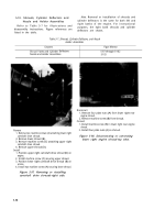
Figure 5-92. Removing fuel injection pump
splined coupler bolts.
5-56
Back to Top


