TM-9-2815-205-24 - Page 231 of 856
INSTALLATION
1.
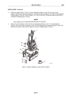
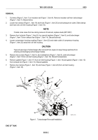
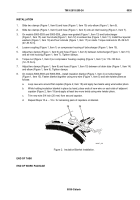
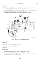
Slide two clamps (Figure 1, Item 19) and hose (Figure 1, Item 20) on air inlet housing (Figure 1, Item 18).
2.
Install new gasket (Figure 1, Item 17) in counter bore of air inlet housing (Figure 1, Item 18).
3.
Install new gasket (Figure 1, Item 10) over studs (Figure 1, Item 13) on exhaust tee (Figure 1, Item 14).
4.
Loosen couplings (Figure 1, Items 23 and 21) on turbocharger (Figure 1, Item 7) and four couplings
(Figure 1, Item 15) on exhaust tubes (Figure 1, Items 16 and 12).
5.
Install turbocharger (Figure 1, Item 7) on studs (Figure 1, Item 13) in exhaust tee (Figure 1, Item 14). Rotate
compressor housing (Figure 1, Item 22), exhaust tee (Figure 1, Item 14), or turbine housing
(Figure 1, Item 11) as required to align components.
6.
Install turbocharger (Figure 1, Item 7), two new lockwashers (Figure 1, Item 6), and two screws
(Figure 1, Item 5) on air inlet housing (Figure 1, Item 18). Torque screws to 46–50 lb-ft (62–68 N·m).
7.
Install four special washers (Figure 1, Item 9) and four new locknuts (Figure 1, Item 8) on studs
(Figure 1, Item 13). Torque locknuts to 35–39 lb-ft (47–53 N·m).
8.
Adjust two clamps (Figure 1, Item 19) and hose (Figure 1, Item 20) over air outlet connection of
turbocharger (Figure 1, Item 7). Tighten clamps.
9.
Torque nut on compressor housing coupling (Figure 1, Item 23) to 110–130 lb-in (12–15 N·m). Torque nut
on turbine housing coupling (Figure 1, Item 21) to 152–168 lb-in (17–19 N·m).
10.
Tighten four exhaust tube couplings (Figure 1, Item 15).
11.
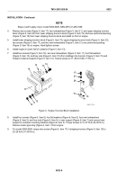
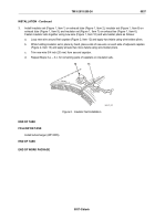
Install insulator set (Figure 1, Item 4) on turbocharger (Figure 1, Item 7) and fasten together using new wire
(Figure 1, Item 1) and wire twister pliers as follows:
a.
Loop new wire around first capstan (Figure 1, Item 1) and apply two twists using wire twister pliers.
b.
While holding insulator set in place by hand, place ends of new wire on each side of adjacent capstan
(Figure 1, Item 3) and apply at least two twists using wire twister pliers.
c.
Trim new wire 3/4 inch (20 mm) from second capstan.
d.
Repeat Steps 11.a. – 11.c. for remaining pairs of capstans.
END OF TASK
END OF WORK PACKAGE
TM 9-2815-205-24
0035
0035-3/blank
Back to Top

