TM-9-2815-205-24 - Page 234 of 856
REMOVAL
1.
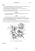
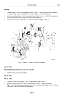
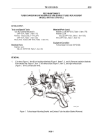
On models 5063-5393 and 5063-539L, cut wires (Figure 1, Item 5) on insulation blanket (Figure 1, Item 4).
Remove blanket from turbocharger (Figure 1, Item 15) and discard wires.
2.
Loosen two clamps (Figure 1, Item 6) and hose (Figure 1, Item 3) connecting turbocharger
(Figure 1, Item 15) to air inlet housing (Figure 1, Item 7).
3.
Loosen two clamps (Figure 1, Item 8) and hose (Figure 1, Item 10) connecting turbocharger oil drain tube
(Figure 1, Item 14) to oil drain elbow (Figure 1, Item 9).
CAUTION
Tape all openings of turbocharger after removal to keep foreign particles from entering and
damaging turbocharger blades.
NOTE
If studs come loose from tee during removal of locknuts, replace studs (WP 0038).
4.
On models 5063-5393 and 5063-539L, remove four locknuts (Figure 1, Item 17), four special washers
(Figure 1, Item 16), turbocharger (Figure 1, Item 15), and gasket (Figure 1, Item 13) from exhaust tee
(Figure 1, Item 11). Discard locknuts and gasket.
5.
Remove two clamps (Figure 1, Item 8) and hose (Figure 1, Item 10) from elbow (Figure 1, Item 9).
6.
Remove two clamps (Figure 1, Item 6) and hose (Figure 1, Item 3) from air inlet housing (Figure 1, Item 7).
1
2
4
3
5
6
7
8
9
10
11
12
13
14
15
16
17
MAINT_094
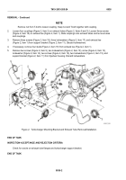
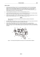
Figure 1.
Turbocharger Removal/Installation.
END OF TASK
TM 9-2815-205-24
0036
0036-2
Back to Top


