TM-9-2815-205-24 - Page 226 of 856
ADJUSTMENT
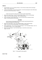
1.
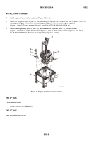
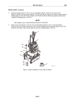
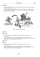
Assemble engine cradle (Figure 1, Item 3) and maintenance stand (Figure 1, Item 10) together using hole
location number 5 (Figure 1, Item 11).
2.
Install four engine mounting brackets (Figure 1, Item 9), eight bolts (Figure 1, Item 6), eight flat washers
(Figure 1, Item 8), and eight new lockwashers (Figure 1, Item 7) to engine block (two bolts per bracket).
Leave brackets loose for adjustment.
1
2
2
4
5
10
11
6
7
8
9
9
3
POSITION OF CRADLE ASSEMBLY
ON MAINTENANCE STAND
MOUNTING BRACKET (NO. 5 HOLE)
MAINT_092
Figure 1.
Engine Maintenance Stand View.
END OF TASK
INSTALLATION
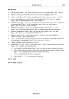
1.
Attach a beam-type sling to engine lifting brackets and lift engine onto maintenance stand
(Figure 1, Item 10).
2.
Install four bolts (Figure 1, Item 1), four new lockwashers (Figure 1, Item 4), eight flat washers
(Figure 1, Item 2), and four nuts (Figure 1, Item 5) in four mounting brackets (Figure 1, Item 9) and side rails
of cradle (Figure 1, Item 3). Tighten stand and bracket bolts.
END OF TASK
REMOVAL
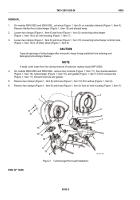
1.
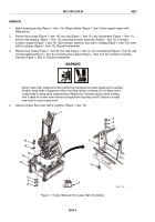
Attach beam-type lifting sling to engine lifting brackets with engine on maintenance stand
(Figure 1, Item 10).
2.
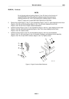
Remove four bolts (Figure 1, Item 1), four lockwashers (Figure 1, Item 4), eight flat washers
(Figure 1, Item 2), and four nuts (Figure 1, Item 5) connecting four mounting brackets (Figure 1, Item 1) to
side rails of cradle (Figure 1, Item 3). Discard lockwashers.
TM 9-2815-205-24
0034
0034-2
Back to Top

