TM-9-2815-205-24 - Page 220 of 856
REMOVAL - Continued
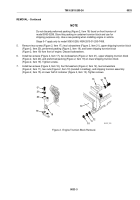
CAUTION
Always install top of container on bottom of container (WP 0010) after the engine has been
removed to avoid weather damage of container.
NOTE
Screw installed in the flywheel housing at eight o'clock position cannot be removed when
the oil filter adapter is installed due to interference.
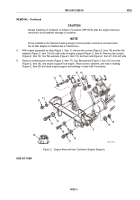
8.
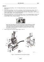
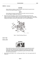
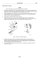
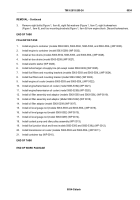
Remove four short screws (Figure 3, Item 25), two long screws (Figure 3, Item 22), two nuts
(Figure 3, Item 26), six lockwashers (Figure 3, Item 24), and rear support (Figure 3, Item 7) from engine
flywheel housing (Figure 3, Item 23). Store screws, washers, and nuts in mailbag (Figure 4, Item 9). Store
mailbag and rear support in lower half of container (Figure 4, Item 13). Discard lockwashers.
22
24
26
24
24
23
7
25
26
MAINT_090
Figure 3.
Engine Rear Support Removal.
END OF TASK
INSTALLATION
WARNING
Never crawl under equipment when performing maintenance unless equipment is securely
blocked. Keep clear of equipment when it is being raised or lowered. Do not allow heavy
components to swing while suspended by lifting device. Exercise caution when working
near a cable or a chain under tension as equipment may drop or shift. Failure to comply
may result in injury to personnel.
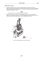
1.
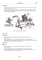
Attach beam-type sling (Figure 4, Item 1) to lifting brackets (Figure 4, Item 2) and support engine with
lifting device.
TM 9-2815-205-24
0033
0033-4
Back to Top

