TM-9-2815-205-24 - Page 213 of 856
REMOVAL - Continued
CAUTION
Always install top of container on bottom of container (WP 0010) after the engine has been
removed to avoid weather damage of container.
NOTE
Screw installed in the flywheel housing at eight o'clock position cannot be removed when
the oil filter adapter is installed due to interference.
5.
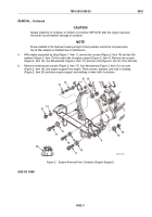
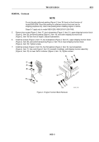
With engine supported by sling (Figure 1, Item 1), remove two screws (Figure 2, Item 18) and two flat
washers (Figure 2, Item 19) from right side of engine support (Figure 2, Item 4). Remove two screws
(Figure 2, Item 14), four flat washers (Figure 2, Item 13), and two nuts (Figure 2, Item 21) from left side.
6.
Remove remaining two screws (Figure 2, Item 17), four flat washers (Figure 2, Item 15), two nuts
(Figure 2, Item 16), and engine support from engine. Place screws, washers, and nuts in mailbag
(Figure 2, Item 20) and store engine support and mailbag in lower half of container.
17
15
17
21
13
15
13
14
15
19
18
4
15
16
20
16
MAINT_085
Figure 2.
Engine Removal from Container (Engine Support).
END OF TASK
TM 9-2815-205-24
0032
0032-3
Back to Top

