TM-9-2815-205-24 - Page 222 of 856
INSTALLATION - Continued
NOTE
Steps 4 and 5 apply only to model 5063-5299, NSN 2815-01-295-7458.
4.
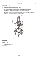
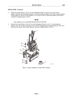
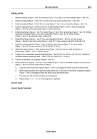
Remove two screws (Figure 5, Item 17), two lockwashers (Figure 5, Item 21), and upper shipping trunnion
block (Figure 5, Item 20) from lower shipping trunnion block (Figure 5, Item 19). Remove preformed packing
(Figure 5, Item 18) from lower shipping trunnion block and install on front of engine.
5.
Install lower shipping trunnion block (Figure 5, Item 19), upper shipping trunnion block (Figure 5, Item 20),
two screws (Figure 5, Item 17), and two new lockwashers (Figure 5, Item 21) over preformed packing
(Figure 5, Item 18) on engine. Hand tighten screws.
6.
Install engine in lower half of container (Figure 5, Item 13).
7.
Install two screws (Figure 5, Item 16), two new lockwashers (Figure 5, Item 11), four flat washers
(Figure 5, Item 12), and two nuts (Figure 5, Item 10) (from mailbag) into trunnion (Figure 5, Item 15) and
forward container support (Figure 5, Item 14). Torque screws to 71–83 lb-ft (96–113 N·m).
15
12
16
12
11
10
13
14
18
17
21
20
19
MAINT_091a
Figure 5.
Engine Trunnion Block Installation.
8.
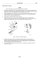
Install four screws (Figure 6, Item 8), four flat washers (Figure 6, Item 6), four new lockwashers
(Figure 6, Item 5), and four nuts (Figure 6, Item 4), in rear support (Figure 6, Item 7) and connect rear
support to container mounting brackets (Figure 6, Item 3). Torque screws to 31–37 lb-ft (42–50 N·m).
Remove beam-type sling (Figure 4, Item 1) from engine.
9.
For model 5063-5299, torque two screws (Figure 5, Item 17) in shipping trunnion (Figure 5, Item 15) to
23–28 lb-ft (31–38 N·m).
TM 9-2815-205-24
0033
0033-6
Back to Top

