TM-9-2815-205-24 - Page 221 of 856
INSTALLATION - Continued
2.
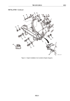
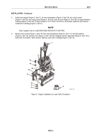
Install rear support (Figure 3, Item 7), six new lockwashers (Figure 3, Item 24), four short screws
(Figure 3, Item 25), two long screws (Figure 3, Item 22), and two nuts (Figure 3, Item 26) on engine flywheel
housing (Figure 3, Item 23). Torque screws to 14–17 lb-ft (19–23 N·m). All screws, washers, and nuts are
contained in mailbag (Figure 4, Item 9).
NOTE
Step 3 applies only to model 5063-5299, NSN 2815-01-295-7458.
3.
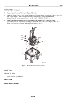
Remove two screws (Figure 4, Item 16), two new lockwashers (Figure 4, Item 11), four flat washers
(Figure 4, Item 12), and two nuts (Figure 4, Item 10) from shipping trunnion assembly (Figure 4, Item 15) in
lower half of container. Store screws, washers, and nuts in mailbag (Figure 4, Item 9).
16
17
12
1
9
14
15
12
13
11
10
2
MAINT_091
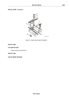
Figure 4.
Engine Installation to Lower Half of Container.
TM 9-2815-205-24
0033
0033-5
Back to Top

