TM-9-2815-205-24 - Page 216 of 856
INSTALLATION - Continued
7.
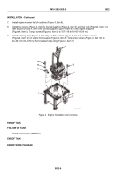
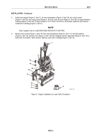
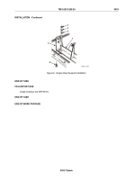
Install engine in lower half of container (Figure 4, Item 8).
8.
Install four screws (Figure 4, Item 3), four flat washers (Figure 4, Item 6), and four nuts (Figure 4, Item 7) in
rear support (Figure 4, Item 4) to connect support (Figure 4, Item 4) to two engine supports
(Figure 4, Item 5). Torque screws (Figure 4, Item 3) to 107–118 lb-ft (145–160 N·m).
9.
Install retaining strap (Figure 4, Item 10), two flat washers (Figure 4, Item 11), and two screws
(Figure 4, Item 12) on engine front support (Figure 4, Item 9). Torque two screws (Figure 4, Item 12) to
24–29 lb-ft (33–39 N·m). Remove beam-type sling (Figure 4, Item 1).
6
7
12
3
1
4
11
10
8
9
5
MAINT_087
Figure 4.
Engine Installation into Container.
END OF TASK
FOLLOW ON TASK
Install container top (WP 0010).
END OF TASK
END OF WORK PACKAGE
TM 9-2815-205-24
0032
0032-6
Back to Top


