TM-9-2815-205-24 - Page 238 of 856
REMOVAL
1.
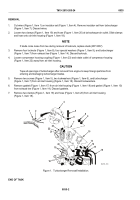
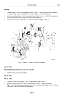
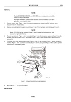
Cut wires (Figure 1, Item 10) on insulator sets (Figure 1, Items 1, 8, and 7). Remove insulator sets from
exhaust tubes (Figure 1, Items 2 and 9) and exhaust tee (Figure 1, Item 6). Discard wires.
2.
Loosen four couplings (Figure 1, Item 3) on exhaust tubes (Figure 1, Items 2 and 9). Slide couplings onto
exhaust tubes and remove couplings, exhaust tubes, and exhaust tee.
3.
If necessary, remove four studs (Figure 1, Item 5) from exhaust tee (Figure 1, Item 6).
1
2
3
4
6
3
3
3
11
11
7
5
7
8
10
9
8
MAINT_096
Figure 1.
Exhaust Tubes and Tee Removal/Installation.
END OF TASK
INSPECTION-ACCEPTANCE AND REJECTION CRITERIA
Check for cracks on exhaust tube flanges.
END OF TASK
INSTALLATION
1.
If removed, install four studs (Figure 1, Item 5) in exhaust tee (Figure 1, Item 6).
2.
Install right exhaust tube (Figure 1, Item 2), left exhaust tube (Figure 1, Item 9), exhaust tee
(Figure 1, Item 6), and four couplings (Figure 1, Item 3) on exhaust manifolds (Figure 1, Item 11). Tighten
nuts (Figure 1, Item 4) on couplings until compressed.
TM 9-2815-205-24
0037
0037-2
Back to Top


