TM-9-2815-205-24 - Page 246 of 856
REMOVAL
NOTE
Models 5063-5392, 5063-5393, and 5063-539L have insulator sets or insulation
covers on exhaust manifolds.
Right and left exhaust manifolds and insulation covers are identical. Use same
procedure to remove both sides.
1.
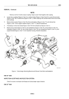
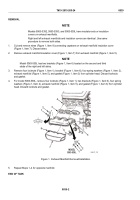
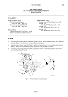
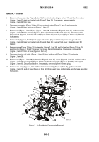
Cut and remove wires (Figure 1, Item 8) connecting capstans on exhaust manifold insulation cover
(Figure 1, Item 7). Discard wires.
2.
Remove exhaust manifold insulation cover (Figure 1, Item 7) from exhaust manifold (Figure 1, Item 5).
NOTE
Model 5063-539L has two brackets (Figure 1, Item 6) located on the second and third
studs of the right and left sides.
3.
Remove four locknuts (Figure 1, Item 1), bracket (Figure 1, Item 6), four spring washers (Figure 1, Item 2),
exhaust manifold (Figure 1, Item 5), and gasket (Figure 1, Item 3) from cylinder head. Discard locknuts
and gasket.
4.
For model 5063-539L, remove four locknuts (Figure 1, Item 1), two brackets (Figure 1, Item 6), four spring
washers (Figure 1, Item 2), exhaust manifold (Figure 1, Item 5), and gasket (Figure 1, Item 3) from cylinder
head. Discard locknuts and gasket.
1
2
3
4
5
2
6
1
7
8
MODEL
5063-539L
MAINT_102
Figure 1.
Exhaust Manifold Removal/Installation.
5.
Repeat Steps 1–4 for opposite manifold.
END OF TASK
TM 9-2815-205-24
0039
0039-2
Back to Top


