TM-9-2815-205-24 - Page 248 of 856
INSTALLATION - Continued
5.
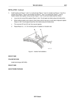
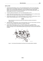
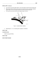
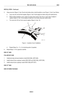
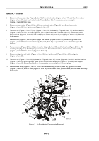
Using new wire (Figure 2, Item 8) and wire twister pliers, install insulation cover (Figure 2, Item 2) as follows:
a.
Loop new wire around first capstan (Figure 2, Item 9) and apply two twists using wire twister pliers.
b.
While holding insulation cover in place by hand, place ends of new wire on each side of adjacent
capstan (Figure 2, Item 10) and apply at least two more twists using wire twister pliers.
c.
Trim new wire 3/4 inch from second capstan (Figure 2, Item 10).
8
9
10
2
MAINT_103
Figure 2.
Insulation Cover Installation.
d.
Repeat Steps 5.a. – 5.c. for remaining pairs of capstans.
6.
Repeat Steps 1–5 for opposite manifold.
END OF TASK
FOLLOW ON TASK
1.
Install glow plug harness brackets (model 5063-539L) (WP 0045).
2.
Install exhaust tube couplings (models 5063-5393 and 5063-539L) (WP 0038).
3.
Install exhaust tube couplings (model 5063-5392) (WP 0037).
END OF TASK
END OF WORK PACKAGE
TM 9-2815-205-24
0039
0039-4
Back to Top

