TM-9-2815-205-24 - Page 247 of 856
CLEANING
Remove loose scale, gasket material, and carbon from exhaust manifolds.
END OF TASK
INSPECTION-ACCEPTANCE AND REJECTION CRITERIA
1.
Check for cracks on exhaust manifolds at holding lug areas.
2.
Check for holes or rusted areas on the exhaust manifold. Discard manifolds with holes.
END OF TASK
INSTALLATION
NOTE
On models 5063-5392 and 5063-5299, exhaust manifold outlet is at front of
engine. Exhaust manifold outlet is at rear of engine on remaining models.
Install exhaust manifold spring washers with crown side facing nut.
Model 5063-539L has two brackets (Figure 1, Item 6) located on the second and
third studs of the right and left sides.
1.
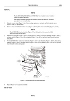
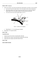
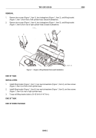
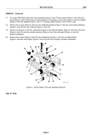
Install new gasket (Figure 1, Item 3), exhaust manifold (Figure 1, Item 5), bracket (Figure 1, Item 6), one
spring washer (Figure 1, Item 2), and one nut (Figure 1, Item 1) over studs (Figure 1, Item 4) in cylinder
head. Install remaining three spring washers (Figure 1, Item 2) and three nuts (Figure 1, Item 1) on studs.
2.
For model 5063-539L, install new gasket (Figure 1, Item 3), exhaust manifold (Figure 1, Item 5), two
brackets (Figure 1, Item 6), four spring washers (Figure 1, Item 2), and four new locknuts (Figure 1, Item 1)
over studs (Figure 1, Item 4) in cylinder head.
3.
Starting with the center stud and working alternately toward each end of manifold, torque locknuts
(Figure 1, Item 1) to 30–35 lb-ft (41–47 N·m).
NOTE
Models 5063-5392, 5063-5393, and 5063-539L have insulating covers on exhaust
manifolds.
4.
Place insulation cover (Figure 1, Item 7) over exhaust manifold (Figure 1, Item 5).
TM 9-2815-205-24
0039
0039-3
Back to Top

