TM-9-2815-205-24 - Page 486 of 856
ADJUSTMENT
EXHAUST VALVE CLEARANCE
1.
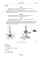
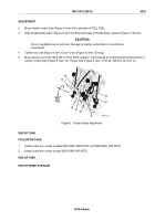
Place speed control lever (Figure 1, Item 2) in idle speed position and secure stop lever (Figure 1, Item 1) in
stop position.
CAUTION
Do not rotate crankshaft in counterclockwise direction using crankshaft bolt. Crankshaft
bolt can loosen and serious engine damage may result if crankshaft bolt is not securely
tightened to crankshaft.
2.
Using crankshaft end bolt, rotate crankshaft clockwise until injector follower (Figure 1, Item 3) is fully
depressed on cylinder to be adjusted.
3.
Hold push rod (Figure 1, Item 8) in position and loosen push rod locknut (Figure 1, Item 7).
NOTE
Normal ambient temperature (cold engine) is 100° F (38° C) or less.
4.
Place 0.026 inch (0.660 mm) thickness gage (cold engine) between end of one exhaust valve stem
(Figure 1, Item 5) and rocker arm bridge (Figure 1, Item 4).
5.
Turn push rod (Figure 1, Item 8) in or out of clevis (Figure 1, Item 6) until a smooth pull is obtained on
thickness gage.
6.
Remove thickness gage. Hold push rod (Figure 1, Item 8) and tighten locknut (Figure 1, Item 7). Lightly tap
rocker arm at bridge (Figure 1, Item 4) with wrench to release friction.
STOP
POSITION
IDLE
POSITION
2
3
4
5
6
7
8
1
MAINT_215
Figure 1.
Adjust Valve Clearance.
TM 9-2815-205-24
0078
0078-2
Back to Top


