TM-9-2815-205-24 - Page 492 of 856
ADJUSTMENT
16.
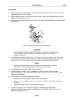
Move speed control lever (Figure 6, Item 2) to FULL FUEL position. If injector rack (Figure 6, Item 27)
becomes tight before speed control lever reaches end of travel, setting is too tight. Loosen locknut
(Figure 6, Item 29) and turn screw (Figure 6, Item 20) slightly counterclockwise. Tighten locknut. Check
setting using Steps 13–14.
17.
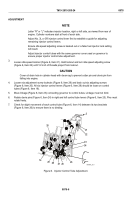
Connect opposite throttle control rod (Figure 6, Item 23) to control tube lever (Figure 6, Item 25) using clevis
pin (Figure 7, Item 24) and cotter pin (Figure 7, Item 30).
18.
Adjust opposite injector control lever (Figure 6, Item 28) per Steps 10–12.
19.
Repeat check on 3L and 3R injector control levers (Figure 6, Item 28) per Steps 13–16. If 3L is loose, adjust
3R again. If 3R is loose, adjust 3R again.
NOTE
Once 3L and 3R injector control levers are adjusted, do not alter their settings. Make
further adjustments only on remaining injector control rack levers.
20.
Hold speed control lever (Figure 7, Item 2) in FULL FUEL position. Check clevis pins (Figure 7, Item 24) for
drag on both right and left control tube lever (Figure 7, Item 25). Both pins should move freely.
21.
With speed control lever still held lightly in FULL FUEL position, adjust 2L and 1L injector control rack levers
(Figure 6, Item 28) per Steps 10–12. Check their adjustment per Steps 13–16. Do not readjust 3L.
22.
With speed control lever still held lightly in FULL FUEL position, adjust 2R and 1R injector control rack
levers (Figure 6, Item 28) per Steps 10–12. Check their adjustment per Steps 13–16. Do not readjust 3R.
23.
Turn idle speed adjusting screw (Figure 6, Item 22) in until it projects 3/16 inch from locknut
(Figure 6, Item 21) to permit starting of engine. Tighten locknut.
24.
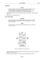
Install new gasket (Figure 8, Item 16), idle speed adjustment screw cover (Figure 8, Item 17), two new
copper flat washers (Figure 8, Item 18), and two bolts (Figure 8, Item 19).
19
18
17
16
MAINT_221
Figure 8.
Idle Speed Adjustment Cover Installation.
THROTTLE DELAY (FOR ALL EXCEPT MODEL 5063-5299)
NOTE
Fill throttle delay reservoir with clean engine oil to lubricate mechanical components. Oil
reservoir need not remain full during adjustment procedure.
1.
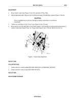
Insert throttle delay timing gage (Figure 9, Item 31) on rack between injector body (Figure 9, Item 12) and
clevis of injector rack (Figure 9, Item 27) on 2R injector.
TM 9-2815-205-24
0078
0078-8
Back to Top


