TM-9-2815-205-24 - Page 487 of 856
ADJUSTMENT
NOTE
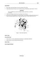
A 0.025 inch (0.635 mm) thickness gage (cold engine) must pass freely between end of
one valve stem (Figure 1, Item 5) and rocker arm bridge (Figure 1, Item 4).
A 0.027 inch (0.686 mm) thickness gage (cold engine) must not pass through bridge
clearance. Mark each rocker arm with a crayon or marker after adjustment.
7.
Check valve bridge clearance with thickness gage. If clearance is not within limits, repeat procedures in
Steps 3–6.
8.
Adjust all exhaust valves following Steps 1–7.
FUEL INJECTOR TIMING
CAUTION
Do not rotate crankshaft in counterclockwise direction using crankshaft bolt. Crankshaft
bolt can loosen and serious engine damage may result if crankshaft bolt is not securely
tightened to crankshaft.
NOTE
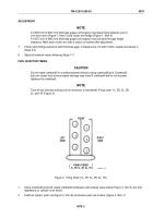
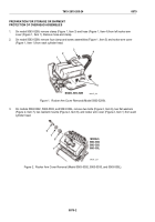
Time all fuel injectors during one full revolution of crankshaft. Firing order: 1L, 3R, 3L, 2R,
2L, and 1R (Figure 2).
1
2
3
1
FRONT
LEFT
VIEW
RIGHT
VIEW
FIRING ORDER
1L, 3R, 3L, 2R, 2L, 1R
2
3
MAINT_216
Figure 2.
Firing Order (1L, 3R, 3L, 2R, 2L, 1R).
1.
Using crankshaft end bolt, rotate crankshaft clockwise until exhaust valve stems (Figure 3, Item 5) are fully
depressed on cylinder to be timed.
2.
Hold fuel injector push rod (Figure 3, Item 8) and loosen push rod locknut (Figure 3, Item 7).
TM 9-2815-205-24
0078
0078-3
Back to Top

