TM-9-2815-205-24 - Page 483 of 856
ASSEMBLY - Continued
CAUTION
Do not press top face of impeller beyond top face of pump housing. Pressing face of
impeller further than top of housing will push impeller into water seal and destroy seal.
3.
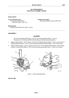
Support pulley end of shaft and press impeller (Figure 3, Item 10) on shaft (Figure 3, Item 13) until impeller
is flush with top face of pump housing (Figure 3, Item 6).
15
9
6
10
13
7
8
MAINT_213
Figure 3.
Coolant Pump Shaft Assembly.
4.
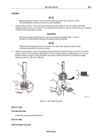
Support pulley (Figure 4, Item 12). Place a short 1/2 inch-diameter rod (Figure 4, Item 16) on impeller end of
shaft and bearing assembly (Figure 4, Item 8). Press shaft into pulley until distance from front face of pulley
to top face of pump housing is 5.60 in. (142.2 mm).
5.
Install new gasket (Figure 4, Item 5), cover (Figure 4, Item 4), and seven bolts (Figure 4, Item 3) on coolant
pump assembly (Figure 4, Item 11). Torque bolts to 72–84 lb-in (8–9.5 N·m).
6.
If removed, install large pipe plug (Figure 4, Item 1) and small pipe plug (Figure 4, Item 2) in coolant pump
assembly (Figure 4, Item 11).
5.60 in.
(142.2 mm)
16
1
8
12
2
3
4
5
11
MAINT_214
Figure 4.
Coolant Pump Assembly.
END OF TASK
TM 9-2815-205-24
0077
0077-5
Back to Top


