TM-9-2815-205-24 - Page 489 of 856
ADJUSTMENT
INJECTOR CONTROL TUBE
1.
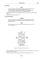
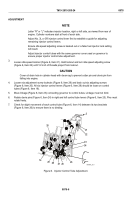
On all except model 5063-5299, loosen two nuts (Figure 4, Item 13) on U-bolt (Figure 4, Item 15) on right
injector control tube (Figure 4, Item 14). Injector control tube must move freely on U-bolt.
13
15
14
MAINT_218
Figure 4.
Injector Timing Adjustment.
2.
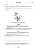
Remove two bolts (Figure 5, Item 19), two copper flat washers (Figure 5, Item 18), idle speed adjustment
screw cover (Figure 5, Item 17), and gasket (Figure 5, Item 16). Discard copper flat washers and gasket.
19
18
17
16
MAINT_217A
Figure 5.
Idle Speed Adjustment Cover Removal.
TM 9-2815-205-24
0078
0078-5
Back to Top


