TM-9-2815-205-24 - Page 490 of 856
ADJUSTMENT
NOTE
Letter “R" or “L" indicates injector location, right or left side, as viewed from rear of
engine. Cylinder numbers start at front of each side.
Adjust No. 3L or 3R injector control lever first to establish a guide for adjusting
remaining injector control levers.
Ensure idle speed adjusting screw is backed out or a false fuel injector rack setting
will result.
Adjust injector control tubes with the same governor cover used on governor to
ensure proper injector control tube adjustment.
3.
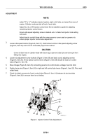
Loosen idle speed locknut (Figure 6, Item 21). Hold locknut and turn idle speed adjusting screw
(Figure 6, Item 22) until 1/2 inch of threads project from locknut.
CAUTION
Cover oil drain hole in cylinder head with clean rag to prevent cotter pin and clevis pin from
falling into engine.
4.
Loosen six adjustment screw locknuts (Figure 6, Item 29) and back out six adjusting screws
(Figure 6, Item 20). All six injector control levers (Figure 6, Item 28) should be loose on control
tubes (Figure 6, Item 18).
5.
Move linkage (Figure 6, Item 23) connecting governor to control tubes. Linkage must not bind.
6.
Rotate clevis pins (Figure 6, Item 24) in right and left control tube levers (Figure 6, Item 25). Pins must
rotate freely.
7.
Check for slight movement of each control tube (Figure 6, Item 14) between its two brackets
(Figure 6, Item 26) to ensure there is no binding.
20
2
21
23
24
25
26
27
28
29
22
14
MAINT_219
Figure 6.
Injector Control Tube Adjustment.
TM 9-2815-205-24
0078
0078-6
Back to Top


