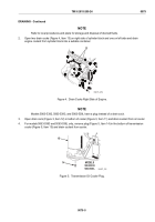
TM-9-2815-205-24 - Page 493 of 856
ADJUSTMENT
2.
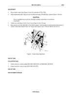
Move injector control tube (Figure 9, Item 14) in direction of FULL FUEL.
3.
Align throttle delay piston (Figure 9, Item 33) flush with edge of throttle delay cylinder (Figure 9, Item 32).
CAUTION
Do not overtighten two U-bolt nuts. Damage to injector control tube or U-bolt clamp
could result.
4.
Tighten two nuts (Figure 9, Item 13) on U-bolt (Figure 9, Item 15) snug.
5.
Move injector rack from NO-FUEL to FULL FUEL position. There should be no binding during movement of
injector control tube (Figure 9, Item 14). Torque nuts (Figure 9, Item 13) to 84–108 lb-in (9–12 N·m).
33
13
31
32
12
15
27
14
FULL
FUEL
MAINT_222
Figure 9.
Throttle Delay Adjustment.
END OF TASK
FOLLOW ON TASK
1.
Install rocker arm covers (models 5063-5392, 5063-5393, and 5063-539L) (WP 0053).
2.
Install rocker arm covers (model 5063-5299) (WP 0052).
END OF TASK
END OF WORK PACKAGE
TM 9-2815-205-24
0078
0078-9/blank
Back to Top


