TM-9-2815-205-24 - Page 574 of 856
ASSEMBLY - Continued
18.
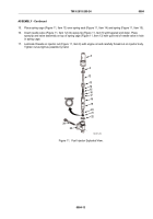
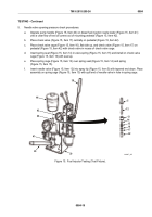
Turn injector over and push rack (Figure 12, Item 24) all the way in.
19.
Place follower spring (Figure 12, Item 7) on injector body (Figure 12, Item 23).
20.
Slide head of plunger (Figure 12, Item 2) into follower (Figure 12, Item 1).
21.
Insert free end of plunger (Figure 12, Item 2) in injector body (Figure 12, Item 23).
22.
Press down follower (Figure 12, Item 1) and slide rack (Figure 12, Item 24) in and out until plunger
(Figure 12, Item 2) falls in place with flat of plunger against flat in gear.
23.
Align slot in follower (Figure 12, Item 1) with stop pin hole in injector body (Figure 12, Item 23).
24.
Place stop pin (Figure 12, Item 3) in slot on injector body (Figure 12, Item 23). Rotate spring
(Figure 12, Item 7) so flat on end of coil is clear of stop pin. Then push stop pin in place while pressing down
on follower (Figure 12, Item 1). Once in place, rotate spring so flat on end of coil is positioned over stop pin.
1
2
7
3
6
23
24
MAINT_285A
Figure 12.
Fuel Injector Assembly.
TM 9-2815-205-24
0084
0084-14
Back to Top


