TM-9-2815-205-24 - Page 576 of 856
TESTING
1.
Injector control rack freeness procedures:
a.
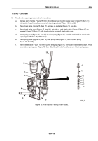
Place injector in injector tip and concentricity gage (Figure 14, Item 37).
b.
Hold rack (Figure 14, Item 24) in NO FUEL position (rack extended all the way out).
c.
Using handle (Figure 14, Item 35), depress follower to bottom of its stroke.
d.
Slowly release pressure on handle (Figure 14, Item 35) while moving rack (Figure 14, Item 24) in and
out until follower reaches top of its travel. Injector passes test if rack falls freely when fully extended
and released.
e.
If rack binds, loosen injector nut, turn tip, and then retighten nut. Loosen and tighten nut several times
if necessary. If rack still binds, change injector nut. Finally, if rack binds, disassemble injector to
eliminate cause of misaligned parts or to remove dirt.
2.
Spray tip concentricity procedures:
a.
Place injector in injector tip and concentricity gage (Figure 14, Item 37).
b.
Adjust dial indicator (Figure 14, Item 36) to zero.
c.
Rotate injector 360 degrees and note total runout as indicated on dial.
d.
If total runout exceeds 0.008 inch (0.203 mm), remove injector from gage. Loosen injector nut, center
spray tip, and torque nut. Check spray tip concentricity again. If, after several attempts, spray tip
cannot be positioned satisfactorily, replace injector nut.
TM 9-2815-205-24
0084
0084-16
Back to Top


