TM-9-2815-205-24 - Page 584 of 856
DISASSEMBLY
NOTE
Match mark blower housing at front and rear end plates before disassembly.
1.
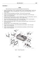
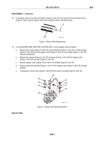
Remove six screws (Figure 1, Item 1), two plates (Figure 1, Item 2), two spacers (Figure 1, Item 24), end
plate cover (Figure 1, Item 23), and gasket (Figure 1, Item 22) from front end plate (Figure 1, Item 7).
Discard gasket.
2.
Wedge a clean folded rag between rotors (Figure 1, Items 9 and 8) to prevent turning.
3.
Remove four self-locking bolts (Figure 1, Item 11) and drive coupling (Figure 1, Item 10) from gear
(Figure 1, Item 12). Discard bolts.
4.
Remove four self-locking bolts (Figure 1, Item 17), retainer (Figure 1, Item 18), coupling (Figure 1, Item 19),
and spacer (Figure 1, Item 20) from gear (Figure 1, Item 21). Discard bolts.
5.
Remove three self-locking bolts (Figure 1, Item 3), thrust plate (Figure 1, Item 4), and three spacers
(Figure 1, Item 25) from front end plate (Figure 1, Item 7). Discard bolts.
6.
Remove two self-locking bolts (Figure 1, Item 5) and two thrust washers (Figure 1, Item 6) from front of
blower. Discard bolts.
7.
Mark gear (Figure 1, Item 12) and gear (Figure 1, Item 21) for reassembly.
8.
Remove twelve-point bolt (Figure 1, Item 14) and blower drive pilot (Figure 1, Item 13) from gear
(Figure 1, Item 12). Discard bolt.
9.
Remove self-locking bolt (Figure 1, Item 16) and blower drive pilot (Figure 1, Item 15) from gear
(Figure 1, Item 21). Discard bolt.
3
4
5
7
8
1
9
10
11
12
13
14
15
16
17
18
19
25
24
23
22
20
21
2
6
MAINT_290
Figure 1.
Blower Disassembly.
TM 9-2815-205-24
0085
0085-2
Back to Top


