TM-9-2815-205-24 - Page 591 of 856
ASSEMBLY - Continued
6.
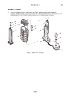
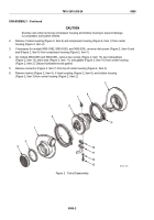
Place rear end plate (Figure 6, Item 30) over rotor shafts. Temporarily install eight flat washers
(Figure 6, Item 44) and eight screws (Figure 6, Item 43) on front end plate (Figure 6, Item 7) and rear end
plate (Figure 6, Item 30) at blower housing (Figure 6, Item 28). Tighten screws until snug.
29
45
44
42
9
43
A
30
28
46
33
8
7
7
8, 9
MAINT_295
Figure 6.
Blower Rotor Assembly.
TM 9-2815-205-24
0085
0085-9
Back to Top


