TM-9-2815-205-24 - Page 593 of 856
ASSEMBLY - Continued
47
48
3
4
5
6
7
8
9
12
14
16
26
25
27
21
47
27
12
9
21
8
MAINT_296
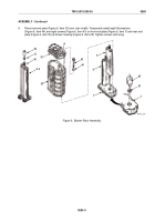
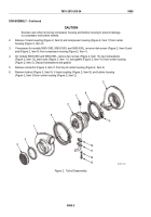
Figure 7.
Blower Left and Right Gear Assembly.
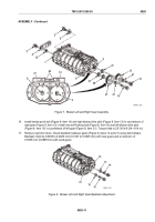
16.
Install twelve-point bolt (Figure 8, Item 14) and right blower drive pilot (Figure 8, Item 13) in counterbore of
right gear (Figure 8, Item 12). Install new self-locking bolt (Figure 8, Item 16) and left blower drive pilot
(Figure 8, Item 15) in counterbore of left gear (Figure 8, Item 21). Torque bolts to 25–30 lb-ft (34–41 N·m).
17.
Remove rag from rotors. Check backlash between gears (Figure 8, Items 12 and 21) using dial indicator.
Backlash must be 0.0005 to 0.0025 inch (0.0127 to 0.0635 mm) with new gears and a maximum of
0.0035 inch (0.0889 mm) with used gears.
12
13
14
15
16
21
MAINT_297
Figure 8.
Blower Left and Right Gear Backlash Adjustment.
TM 9-2815-205-24
0085
0085-11
Back to Top

