TM-9-2815-205-24 - Page 596 of 856
ASSEMBLY - Continued
24.
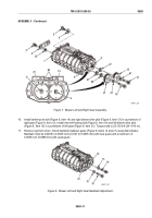
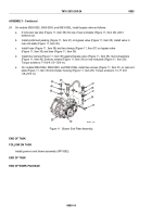
On models 5063-5392, 5063-5393, and 5063-539L, install bypass valve as follows:
a.
If removed, tap tube (Figure 11, Item 39) into top of rear end plate (Figure 11, Item 30) until it
bottoms out.
b.
Install preformed packing (Figure 11, Item 41) on bypass valve (Figure 11, Item 35). Install valve in
rear end plate (Figure 11, Item 30).
c.
Install hose (Figure 11, Item 38) and two clamps (Figure 11, Item 37) on bypass valve
(Figure 11, Item 35) and tube (Figure 11, Item 39).
d.
Install two clamps (Figure 11, Item 36) against bypass valve (Figure 11, Item 35), two lockwashers
(Figure 11, Item 40), and two screws (Figure 11, Item 34) on rear end plate (Figure 11, Item 30).
Torque screws to 7–9 lb-ft (10–12 N·m).
e.
On models 5063-5392, 5063-5393, and 5063-539L, install two screws (Figure 11, Item 31) on rear end
plate (Figure 11, Item 30) into blower housing (Figure 11, Item 28). Torque screws to 13–17 lb-ft
(18–23 N·m).
36
35
31
41
34
39
38
37
36
40
37
28
30
MAINT_300
Figure 11.
Blower End Plate Assembly.
END OF TASK
FOLLOW ON TASK
Install governor and blower assembly (WP 0062).
END OF TASK
END OF WORK PACKAGE
TM 9-2815-205-24
0085
0085-14
Back to Top


