TM-9-2815-205-24 - Page 604 of 856
ASSEMBLY - Continued
10.
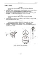
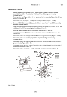
Place turbine wheel assembly (Figure 7, Item 16), wheel shroud (Figure 7, Item 17), center housing
(Figure 7, Item 2), and backplate (Figure 7, Item 20) upright in turbocharger holding fixture.
11.
With compressor wheel (Figure 7, Item 15) at room temperature, position it over shaft of turbine wheel
assembly (Figure 7, Item 16).
CAUTION
Turn compressor wheel nut with a double universal socket to prevent bending turbine
wheel shaft.
12.
Lubricate threads of turbine wheel assembly (Figure 7, Item 16) and wheel face on compressor wheel
(Figure 7, Item 15) with engine oil. Install new locknut (Figure 7, Item 14). Torque nut to 125–150 lb-in.
(14–17 N·m) to seat compressor wheel against thrust spacer.
13.
Loosen locknut (Figure 7, Item 14) and inspect nut face and front face of compressor wheel to ensure they
are smooth and clean.
14.
Torque locknut (Figure 7, Item 14) to 35–55 lb-in. (4–6 N·m).
15.
Turn locknut (Figure 7, Item 14) an additional 120–130 degrees.
16.
Check bearing axial end play as follows:
a.
Clamp center housing assembly in soft-jawed vise.
b.
Fasten magnetic base dial indicator (Figure 7, Item 34) to center housing with indicator tip resting on
end of rotating shaft on compressor side.
c.
Move shaft axially back and forth by hand. Total indicator reading should be between
0.003 and 0.010 inch (0.07 to 0.25 mm). Replace shaft assembly if readings are not in limits.
14
15
20
2
17
34
16
MAINT_307
Figure 7.
Turbo Turbine Assembly.
TM 9-2815-205-24
0086
0086-8
Back to Top


