TM-9-2815-205-24 - Page 605 of 856
ASSEMBLY - Continued
17.
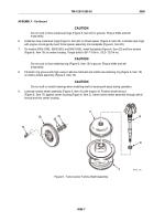
Check shaft radial movement as follows:
a.
Bolt dial indicator adapter (Figure 8, Item 36) to oil drain tube mounting pad.
b.
Mount magnetic base dial indicator (Figure 8, Item 34) on dial indicator adapter (Figure 8, Item 36).
c.
Place dial indicator tip against indicator adapter rod (Figure 8, Item 35).
NOTE
Ensure adapter rod (Figure 8, Item 35) does not contact sides of center housing or
readings are invalid.
d.
Grasp ends of rotating assembly and apply equal pressure at each end, moving rotating shaft toward
and away from dial indicator. Crosswise movement must be between 0.003 and 0.007 inch
(0.07 to 0.17 mm).
34
35
36
MAINT_308
Figure 8.
Turbo Radial Movement Check.
TM 9-2815-205-24
0086
0086-9
Back to Top

